
TM11-5895-846-14
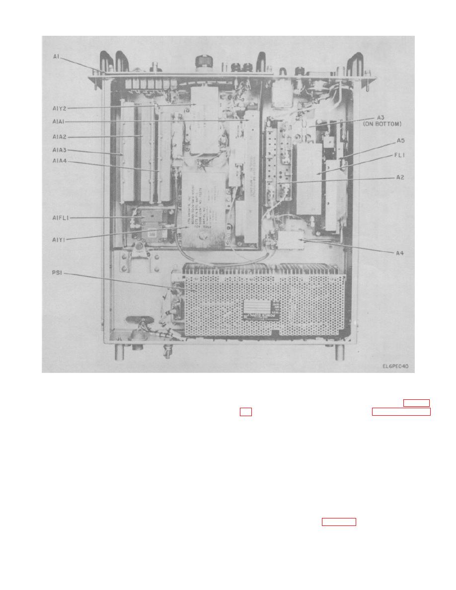
Figure 5-14. Upconverter Module Locations.
(2) Place the IF IN switch in the 70 MHz
(6)
If no IF IN is indicated, remove and
position and observe the MONITOR meter for an
replace the 70/700 MHz upconverter module A2 (para 5-
indication of 15 to 35. If the indication is correct, proceed
to step (7) below. If the indication is incorrect, proceed
below and perform the gain adjustments.
to step (3) below.
(7) Place the MONITOR switch to the 700
(3) Disconnect the modem drive cable from
OUT position. (IF IN switch is still in 70 MHz position)
the 70 MHz connector on the front panel.
(8) Observe the MONITOR meter for an
(4) Place and momentarily hold the TEST
indication of 5 to 45. If the indication is correct, proceed
OSC switch in the ON position. Observe the MONITOR
to step (10) below. If the indication is incorrect, proceed
meter for an IF input indication.
to step (9) below.
(5) If an IF input is indicated, the problem is
(9) Place and momentarily hold the APC
very likely inadequate 70 MHz drive from the modem.
switch on the SHF filter/detector module A5 in the test
Replace the drive cable back on the 70 MHz IF IN
position. Observe the MONITOR meter. If the indication
connector. No further testing is necessary.
is correct, proceed to step (10) below. If the indication is
incorrect, remove and replace the 70/700 MHz
upconverter module A2 (para 5-25b).
5-36

