
TM 11-5895-846-14
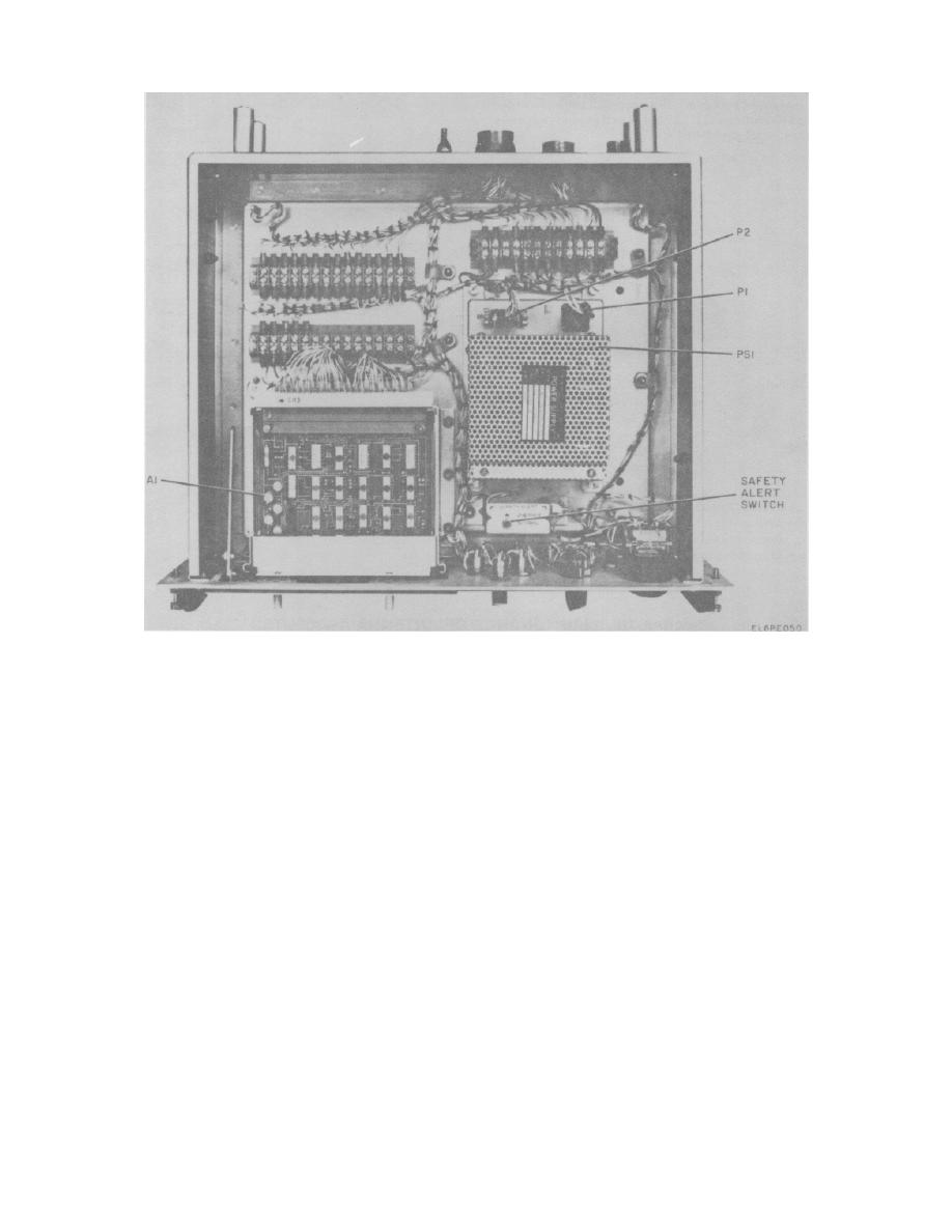
Figure 5-24. Alarm Monitor, Module Locations.
a. Removal and Replacement of Power Supply
b. Removal and Replacement of Fault/Safety
Module PS1.
Gate A1.
(1) On the alarm monitor, place the POWER
(1) On the alarm monitor, open the FAULT
circuit breaker to the OFF position.
OVERRIDE/MODULE ACCESS cover.
(2) Loosen the four captive screws on the
(2) Grasp the two ejector handles on the front
front panel.
of the board, pull the handles outward to unplug the
(3) Open the alarm monitor drawer.
board and then pull out the board.
(4) On the module, remove chassis cable
(3) Remove the board through the front panel
connector P1 from module connector (PS1)J1.
access cover.
(5) On the module, loosen the two captive
(4) Replace the board by performing steps
screws which secure chassis cable connector P2 and
(1), (2) and (3) above in reverse order.
remove it from module connector (PS1) J2.
(6) From the top of the chassis, loosen and
5-46.
Removal
and
Replacement
of
Alarm
remove the four captive screws that secure the module
Monitor
to the chassis. Remove the module.
(7) Replace the power supply module by
a. On the alarm monitor front panel, place the
performing steps (1) through (6) above in reverse order.
POWER circuit breaker to the OFF positions.
b. Loosen the four captive screws on the front
panel.
5-67

