
TM11-5895-846-14
(2) On the antenna control, place the
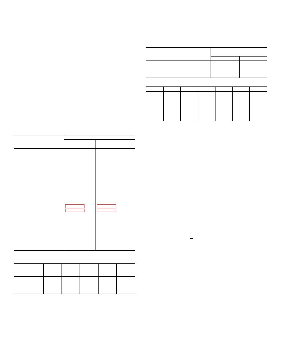
Table 5-6. Anolg Card (A6) Meter Test, CB-3 (DC PWR
MONITOR switch to the CARRIER LEVEL position, the
60V) OFF
TRACK SIGNAL/IF-VIDEO switch to IF, and the POWER
switch to the ON position. On the remote control, place
AXIS CONTROL COMMAND
MONITOR Meter Switch
the MODE switch to the MANUAL position.
Position A6
(3) Observe on the antenna control that the
EL
X-EL
POWER indicator is illuminated, and on the remote
Right
0
100
control the REMOTE ON indicator is illuminated.
Left
0
-100
Also on both units the TRACK SIG LOSS
Up
100
0
Down
-100
0
indicators will be illuminated if there is no signal present.
(4) On the remote control, operate the AXIS
Table 5-7. Autotrack Circuit Card (A4)LED Indicator Sequence
CONTROL switch to the following positions and observe
*Step
DS1
DS2
DS6
DS3
DS5
DS4
the antenna operation.
1
1
1
1
1
0
0
2
0
0
1
0
0
0
3
1
1
0
0
0
0
Position
Indication
4
0
0
0
0
0
0
UP
Antenna travels up in elevation
5
1
1
1
1
0
0
DOWN
Antenna travels down in elevation
6
1
1
1
1
0
1
L
Antenna travels left in cross elevation
7
0
1
1
1
0
0
R
Antenna travels right in cross elevation
NOTE
Table 5-4. Monitor Meter Normal Indications
*Always begin in the X-EL axis (DS5-OFF,
Meter Indication
shown as 0 in step 1). Each step should be
MONITOR Switch Position
0.5 second in duration with the exception of
8-Foot Antenna
20-Foot Antenna
step 7 which is a random interval of 0 to 8
PS-2
+ 60V
55-70
55-70
+ 24 V
20-32
20-32
{
seconds. After step 7, the sequence should
PS-1
- 15 V
- 24 (- 36)
- 24 - (- 36)
repeat steps 1 through 6 but with DS5 ON,
+15 V
24 - 36
24 - 36
thus stepping in the EL axis.
+5
44 - 56
44 - 56
X -ELA9V
L = +10 2
L = +55 +10
(5) On the remote control, place the MODE switch
R = -10 2
R = -55 10
to the ACQ position and operate the AXIS CONTROL
X-ELA9A
L = +5 1
L =+15 3
switch to the same positions as in step (4) above and
R = -5 1
R = -15 3
observe for the same indications.
X-ELA6
L = -7 3
L = -18 4
R = +7 3
R = +18 4
NOTE
X -EL TACH
L = -40 8
L = -75 12
If a signal is acquired, antenna travel will
R = +40 8
R = +75 12
stop and the AXIS CONTROL switch will no
X - EL POT
longer drive the antenna.
EL POT
ELA8A
U = -10 3
U = -20 6
(6) On the remote control, place the MODE switch
D = +5 2
D = +10 3
to the AUTO position and observe the antenna. The
EL A8V
U = -10 3
U = -44 6
antenna will scan in one axis (elevation or cross
D = +10 3
D = +40 6
elevation) for one minute.
This motion is barely
ELA6
U = +6 3
U = +20 5
D = -6 3
D = -20 5
perceptible (about + 0.5 inches at the edge of the
EL TACH
U = +40 6
U = +70 8
antenna).
D = -40 6
D = -70 8
(7) If any of the indications in steps (3) through (6)
Carrier
0 to +90
0 to +90
above are not correct and the antenna control has no
faults, the problem is in the remote control or its cabling;
Table 5-5. Mode Logic (A5) LED, Normal Indication
proceed to step (8) below.
AXIS
(8) Remove and replace the remote control or
CONTROL
DS8
DS10
DS5
DSS7
DS6
remove the remote control and continue operation
Command
without it.
Left
Off
On
Off
Off
On
Right
Off
On
Off
On
On
Up
On
Off
On
On
Off
5-14.
Removal and Replacement of Antenna
Down
On
Off
On
Off
Off
Control
a.
Place POWER AC switch in the OFF position
b.
Loosen the four captive screws holding the
drawer to the rack.
5-7
