
TM11-5895-846-14
The power amplifiers are left on standby.
8399 MHz respectively. Output levels should be at least
(8) Set the sythesizer to 8399 MHz and
50 dB above input to 20 dB coupler.
measure and record the signal level.
(16) The output level of the 70 MHz may be
(9) Repeat step (8) above at 8200 MHz.
adjusted if necessary at the 700/70 MHz mixer assembly
(10) Repeat step (8) above at 7950 MHz.
A2A1 in the downconverter drawer, with the receiver gain
(11) Disconnect the loop test cable from the
adjustment control R5 or MDL gain control R6. Follow
power meter and connect it through the 14 dB attenuator
procedure in step (18) below.
to the LOOP TEST coupler.
(17) The output level of the 700 MHz may be
(12) Calculate and record the input levels for
adjusted if necessary at the 700 MHz preamp assembly
each frequency by subtracting 14 dB from the measured
A3A2 in the downconverter drawer with pots R8 and R9.
levels of steps (8), (9), and (10) above.
Follow procedure in step (19) below.
(13) Connect the power meter with the
NOTE
HP8481A head to the 70 MHz OUTPUT (J4) of the
During this procedure, units are
downconverter to be measured.
extended from the rack.
As
(14) Read and record, the measured level.
necessary, open the adjacent cable
The level should be at least 50 dB above the level
trough access doors to relieve strain
calculated in step (12) above.
on the terminal cables.
(15) The overall receive gain may be measured
for receive frequencies of 7270 MHz and 7699 MHz by
tuning the upconverter synthesizer to 7970 MHz and
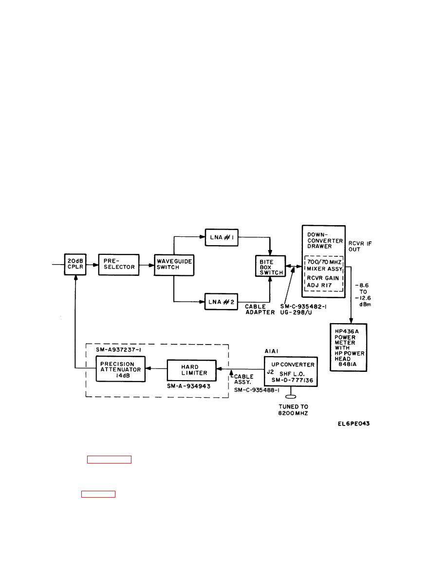
Figure 5-17. Downconverter, Receiver Gain Adjustment Diagram.
NOTE
Refer to table 5-10 for accessory items
required to perform the gain adjustment
procedure. These items are stowed in bags
inside the shelter, unless noted otherwise.
Refer to table 2-1 for stowage locations.
5-48
