
TM 11-5895-846-14
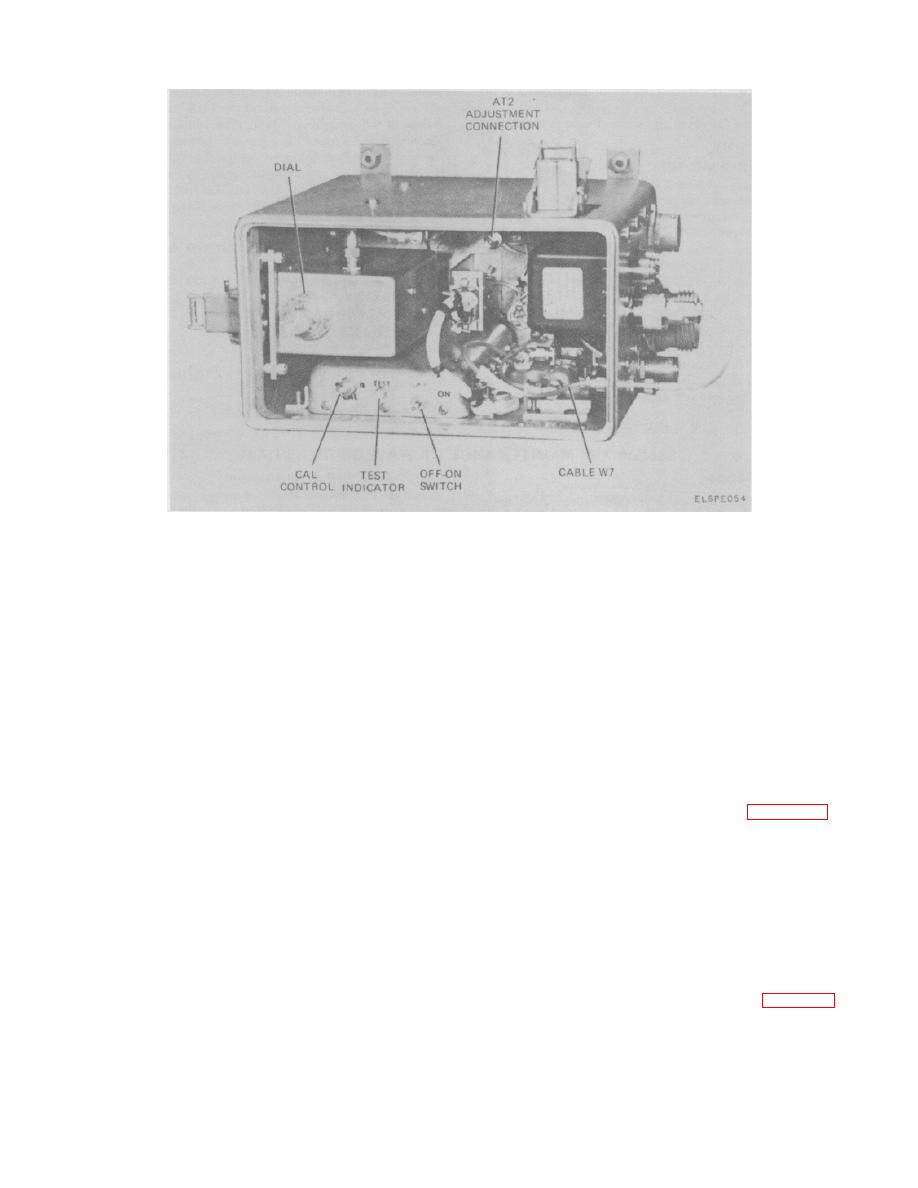
Figure 5-28. LNA BITE, Adjustment Items.
a. At the LNA control/translator check that the
dial setting for that frequency. The frequency used for
test should be one that will not interfere with the
POWER circuit breaker is in the ON position and all
communications channel. A good practice would be to
power supply voltages are normal.
keep the test frequency at 7510 MHz as long as the
communications channel is not operating in this range.
WARNING
e. Loosen the jam nut on the CAL control.
To perform the following procedures, it
f.
Place the OFF-ON switch to the ON position
is necessary to have access to the LNA
and hold it in that position while completing the
BITE mounted on the antenna center
adjustment of steps g and h below.
section. Be careful not to disturb the
g. Adjust the CAL control until the TEST indicator
cabling
or
the
other
mounted
is illuminated.
electronics.
Avoid any radiation
h. Slowly readjust the CAL control until the TEST
exposure; do NOT go in front of the
indicator is just extinguished.
i.
If steps g and h above cannot be performed,
the LNA BITE should be replaced (para 5-56) and
CAUTION
returned to the next higher level of maintenance.
Never operate the STBY LNA TEST/TEST
j.
Tighten the jam nut on the CAL control. Do not
switch to the ON position while the
change the adjustment when tightening the nut.
adjustment is being performed. This
k. Return cable W7 to its operational position
could cause damage to the indicator
using the torque wrench.
lamp in the LNA BITE.
I.
The standby LNA may now be tested at the
LNA BITE utilizing the switch and indicator lamp.
b. Release the two snap fasteners which secure
m. If a faulty LNA is indicated, switch to the other
the cover on the LNA BITE and open the cover.
LNA and test it. If only one LNA shows a fault check that
c. Remove cable W7 from its operational position
you can get receive signals.
If good signals are
(inside of STANDBY LNA RETURN connector) and
received, check the coaxial tranfer switch (para 5-55).
connect it to the adjustment connection at AT2.
d. Refer to the calibration chart in the top cover.
The three digit number next to a frequency indicates the
5-75
