
TM 11-5895-846-14
d. Auxiliary IF Circuits. Four auxiliary IF circuits
the terminal to meet mission requirements, in
connecting test equipment, and in emergency routing
are accessible at the outside wall of the shelter. These
around a malfunctioning unit.
circuits may be used at either 70-MHz or 700-MHz and
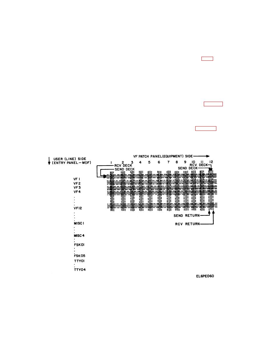
g. Central Distribution Frame.
The central
are routed to the IF patch panel where they may be
distribution frame (CDF) is a terminating device
patched to the up or down converters directly.
e. Orderwire. The orderwire unit is coupled
electrically located between the VF/TTY signal entry
panel-MDF assembly and the VF and the TTY patch
through the VF patch to the multiplexer. The orderwire
panels, as shown in figure FO-4. Echo-suppressor-
requires one VF channel in the multiplexer.
f.
Signal Distribution. The baseband equipment
disable leads also terminate at the CDF assembly. The
CDF provides the operator with a facility to reconfigure
provides the subscriber with the following possible
any VF/TTY user channel on the out- station side of the
communications circuits:
terminal onto any channel position on the VF and TTY
( 1) 12 duplex voice-frequency circuits.
patch panels. The latter is limited to TTY low-level or
( 2) 9 duplex teletype circuits.
FSK users. (High-level TTY users are routed from the
( 3) 4 duplex 0 to 20-kb/s synchronous circuits.
entry panel to line isolators.) The principal element of the
( 4) 2 duplex 50-kb/s synchronous circuits.
CDF is a 48/48 by 8-deck matrix board. This device is
( 5) 2 duplex 56-kb/s synchronous circuits.
illustrated diagrammatically in figure 6-6. The 12 echo-
( 6) 2 duplex 64-kb/s synchronous circuits.
suppressor-disable leads terminate at the patch panel
( 7) 2 duplex 128-kb/s synchronous circuits.
side of the matrix board and can be routed through the
( 8) 2 duplex 256-kb/s synchronous circuits.
CDF to users via VF external lines if required.
( 9) 1 duplex 512-kb/s synchronous circuit.
Reconfiguration of the matrix board is accomplished by
(10) 1 duplex 512-kb/s synchronous circuit.
inserting a program pin (fig. 6-7) into the proper
The VF and TTY (except high-level TTY) circuits are
crosspoint. This pin effects the crosspoint connection
routed within the terminal by a central distribution frame
(a manually-programmed crosspoint matrix) and four
panels. These units provide great flexibility in configuring
Figure 6-6. CDF Reconfiguration Matrix, Function Diagram.
6-12

