
TM 11-5895-846-14
EL6PE157
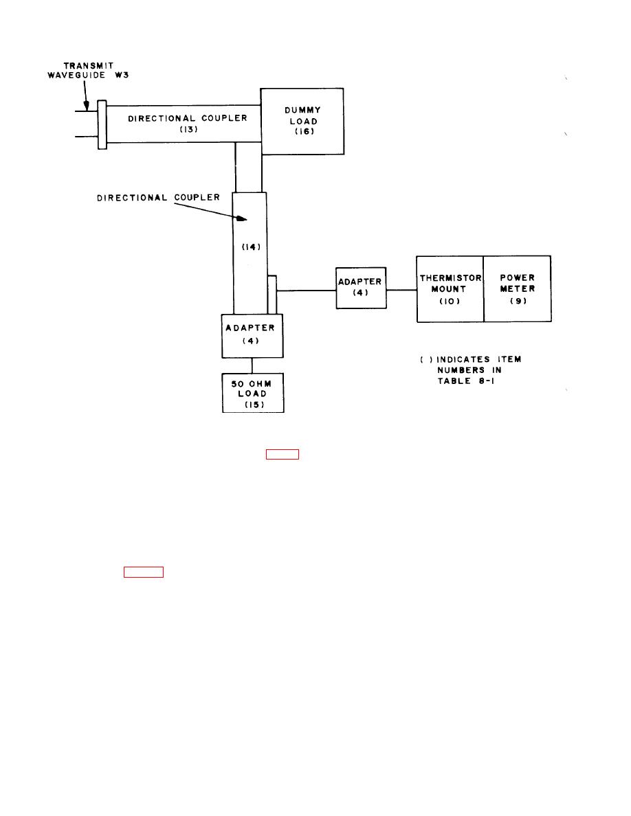
Figure 8-4. -Transmitter Power Output Test Setup.
b. Connect the test equipment as shown in figure
adjust the on-line power amplifier OUTPUT LEVEL
control for a 1000 watt reading on the PA MONITOR
8-4. Apply power to the test equipment and allow it to
meter.
warm up for approximately 5 minutes.
h. The test equipment power meter should read 0 +
c. Tune the upconverter and power amplifier to
1.5 dBm. Note the reading.
8100 MHz.
i. Continue to hold the SAFETY ALERT switch and
d. Note the on-line status of the transmitter groups.
return the PA power output to the assigned level; release
On the on-line power supply place the
the switch.
OPERATESTANDBY switch to the STANDBY position.
j. On the on-line power supply, place the
e. Disconnect the transmit waveguide, W3, from
OPERATE-STANDBY switch to the STANDBY position.
the antenna and connect it to the test equipment
k. On the standby power supply, place the
directional coupler (fig. 8-4).
f. On the on-line power supply, place the
OPERATE-STANDBY switch to the STANDBY position.
l. Position the transmit waveguide switch to place
OPERATE-STANDBY switch to the OPERATE position.
the standby PA on-line.
m. Repeat steps f, g. and h above for the standby
WARNING
transmitter group then proceed to step n below.
1000 WATTS OF RADIATED RF
n. If both readings are out of tolerance, fault isolate
POWER. DO NOT operate the alarm
the common waveguide system. If one reading only is
monitor SAFETY ALERT switch when
out of tolerance, fault isolate to the PA and associated
the
transmit
waveguide
is
waveguide.
disconnected from either the antenna
or the test equipment.
g.Open the alarm monitor drawer. While holding the
SAFETY ALERT switch in the OVERRIDE position,
8-8

