
TM 11-5895-846-14
CHAPTER 2
SERVICE UPON RECEIPT AND INSTALLATION
Section I. SYSTEMS PLANNING
2-1.
Scope
2-3.
Description of Communications Network
This chapter provides the information and instructions
necessary to select a terminal site assemble and point
the AS-3036/TSC antenna, ground the equipment, and
The
multicarrier
operation
is
provided
when
to interconnect signal and power cables and external
intermodulation free Antenna AS-3199/TSC is used as
connections.
the radiating element. The individual tracking signals car
function using communications signal or satellite beacon
signal. Tracking signal selection is made per mission
2-2.
System Interface Capability of Terminal The
profile or at the operator's discretion.
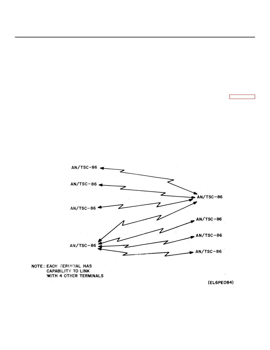
field user interface equipment accepts voice frequency
illustrates typical deployment of the communications
(VF), teletype (TTY), baseband digital signals and
network.
externally modulated 70 or 700 MHz signals through
shelter entry panels. The various types of defense
2-4. External Connection Interface
communications systems field user equipments and the
radio subsystem are interfaced via the communications
subsystem group.
Six shelter entry panels provide the major terminals for
external connection interface for full operation in the
network. These terminals provide connections for the
telephone, external IF, 5 MHz standard, VF TTY, TTY
TX/RX, SHF IN/OUT, antennas, AUX LNA BITE, LNA,
elevation, cross elevation, loop test, remote antenna
control, and main power inputs 1 and 2.
Figure 2-1. Typical Terminal Communications Network.
2-1
