
TM 11-5895-846-14
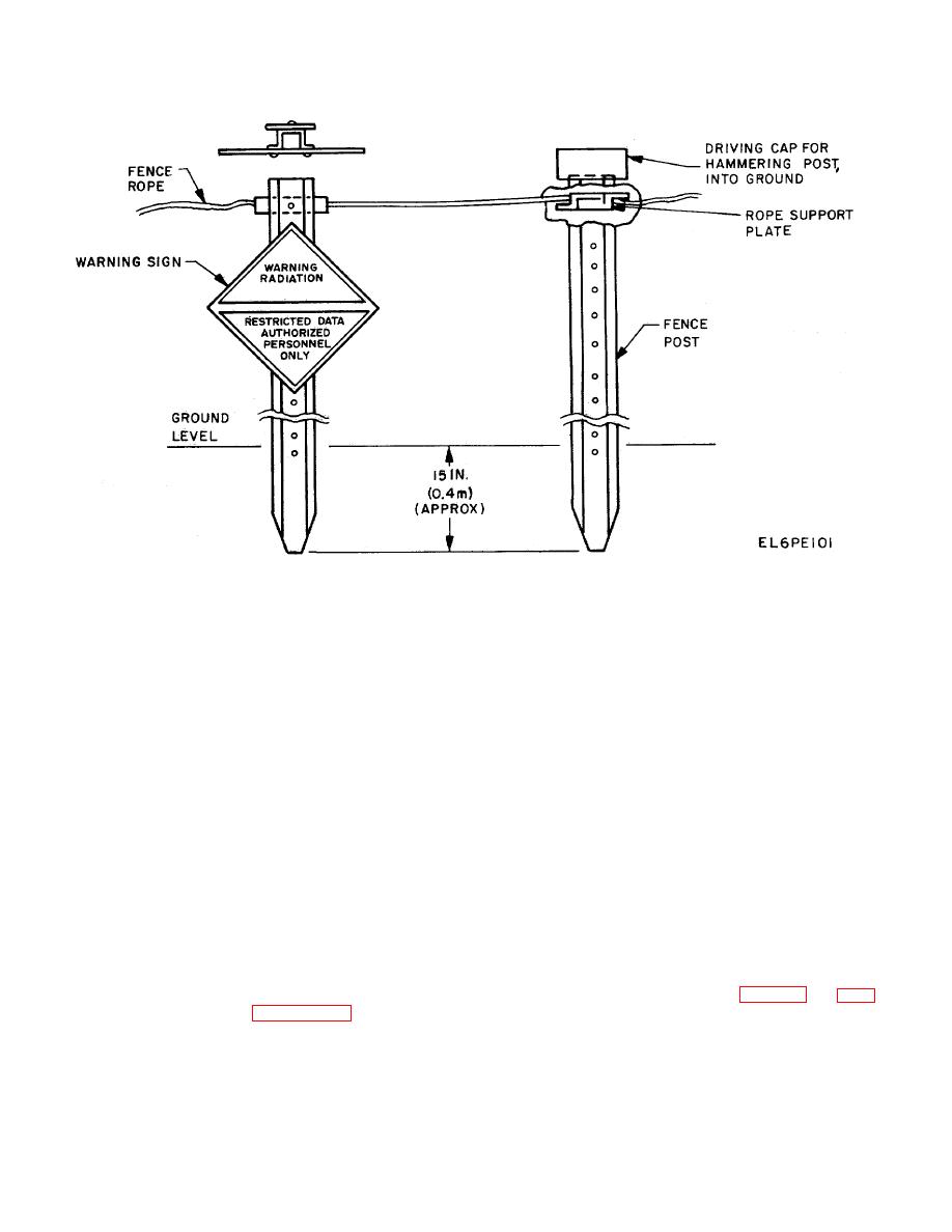
Figure 2-13. Hazard area Fence Posts, Rope and Warning Signs; Assembly Details.
e. Using the above third fence post as a
2-19. Anchoring the Antenna and Shelter
reference, locate and drive one each of two corner fence
a. Factors to be Considered. Due to the close
posts 19 feet (5.8m) on either side of the reference fence
spacing of the antenna and shelter as well as weather
post and at right angles to the sighting line. Orientation
conditions around the site area, the following should be
shall be the same as for the reference fence post.
considered prior to performing any anchoring
f.
Lay out the rope on the ground and around the
procedures:
five fence posts starting and ending at the 16 inch side
(1) Anchor the antenna if winds in excess of
ground pads. Momentarily place tension on the entire
15 miles per hour (24 kph) are expected or if the terminal
rope loop to straighten the side runs to each corner
is to be operated for a considerable period of time.
fence post. Balance out the excess rope at the two
Anchor the shelter if winds in excess of 40 miles per hour
ends.
(64 kph) are expected.
g. Using the rope side runs as a marker line,
(2) The shelter tie-down assemblies must not
locate three fence posts on each side (six total) on 15-
interfere with the antenna structure or its tie-down
foot (4.6m) centers starting from the corner fence posts.
assemblies.
h. Orient the front of these fence posts to face
(3) The shelter anchors must be placed at
away from the hazard area and then drive them into the
least 5 feet (1.5m) from the antenna anchors so that
ground. Replace the driving cap in its stowage bag.
each will load an independent volume of soil.
i. Starting at one end, thread the rope through the
(4) Try to minimize the effects of hammering
notches of the rope support plate of the first fence post.
j.
Attach the rope to the remaining fence posts in
frequently and with lighter strokes rather than bulldozing
them into the ground with fewer but much heavier
turn. Leave a slight loop drop between fence posts;
strokes.
extreme tension is not required.
k. Attach the six warning signs to the selected
fence posts as shown in figure 2-12. Engage the
elongated holes in each warning sign on the support
studs on front of each fence post.
2-29
