
TM 11-5895-846-14
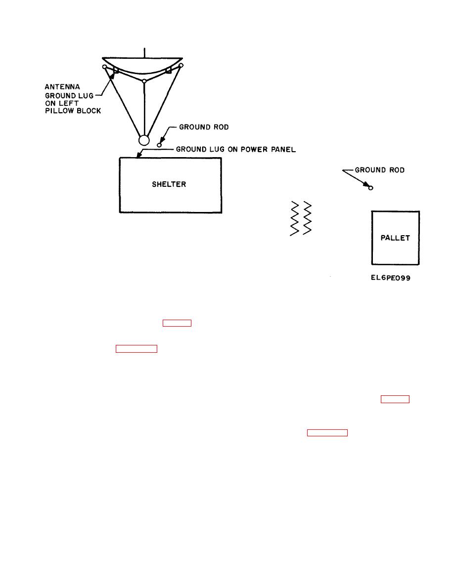
Figure 2-11. Ground Rod Locations.
two (their power connections) may not exceed 40 feet.
2-17. Installing Ground and Power Cables (fig. 2.11)
Two W5 cables (50 feet each) connect between Main
a. Power Pallet Primary Power.
Power 1 and 2 of the shelter to Load Feed-i and Load
(1) Remove the following items (fig. 2-4):
Feed-2 of the switch box.
(a) Ground rods (two sets).
b. Base or Commercial Primary Power. When
(b) Hammer (2) Drive two ground rods at
120/208, 3-phase, 4-wire, 50/60 Hz base or commercial
the locations as shown in figure 2-11. Using a ground
power is available the following procedure is followed.
clamp, securely fasten the stripped ends of the shelter
(1) The power drop must be within 40 feet of
ground cable (W7) and antenna ground cable (W9) to
the shelter.
the shelter ground rod.
(2) Power drop connections should accept
(3) At the shelter power entry panel connect
3/8 inch ring terminals.
the terminal lug end of the shelter ground cable (W7) to
(3) Remove the following items (fig. 2-4):
the GROUND lug. Tighten the wing nut securely.
(a) Ground rods (two sets).
(4) At the antenna connect the terminal lug
(b) Hammer.
end of the antenna ground cable (W9) to the wing-nut
(4) Drive two ground rods; one near the
ground lug on the left pillow block.
shelter as shown in figure 2-11 and the other near the
(5) Using a ground clamp, securely fasten the
base power drop. Using a ground clamp, securely fasten
stripped end of the power ground cable (W8) to the pallet
the stripped ends of the shelter ground cable (W7) and
ground rod.
antenna ground cable (W9) to the shelter ground rod.
(6) At the power pallet, connect the terminal
(5) At the shelter power entry panel connect
lug end of the ground cable (W8) to the ground lug of the
the terminal lug end of the shelter ground cable (W7) to
power switch box. Tighten the wing nut securely.
the GROUND lug. Tighten the wing nut securely.
(7) Connect the primary power cable between
(6) At the antenna connect the terminal lug
the shelter and power pallet. The distance between the
end of the antennal ground cable (W9) to the wing-nut
lug on the left pillow block.
2-26
