
TM 11-5895-846-14
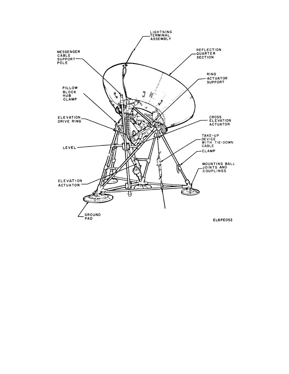
Figure 5-26. Antenna, Location of Components.
(1) Disconnect the cable from the actuator.
The quick-release pins are equipped
(2) Slightly rock the antenna to relieve strain
with automatic locking pins to hold the
on the actuator rod end.
handles in a closed position. Exercise
(3) Unlock, release, and remove the quick-
care to release the locking pins before
release pin which holds the actuator rod end to the
attempting to raise the handles.
elevation drive ring. Maintain control of both the actuator
and the antenna.
NOTE
5-69
