
TM 11-5895-846-14
Figure 5-4. Power Amplifier, Module A1 Captive Screws.
a. Removal and Replacement of RF Low Power
(4) Loosen the eight captive screws on the
Alarm Module A1.
front panel of the PA.
(5) Pull on the two handles to extend the PA
(1) Observe the warning note under
from the rack.
paragraph 5-18 above.
(6) Loosen the twelve 1/4-turn fasteners
CAUTION
which secure the top cover and remove the cover.
Handle the waveguides below with
(7) Remove module connector P1 from
care. If damaged, they may cause
chassis cable connector J5 (fig. 5-3).
equipment
malfunction.
Also,
NOTE
remove your wristwatch to prevent it
If connectors J5 and P1 cannot be
from becoming magnetized.
separated easily, refer to c below and
(2) On the power amplifier (PA), unlock the
remove the flexible plenum.
quick disconnect clamp securing the PA SHF OUT
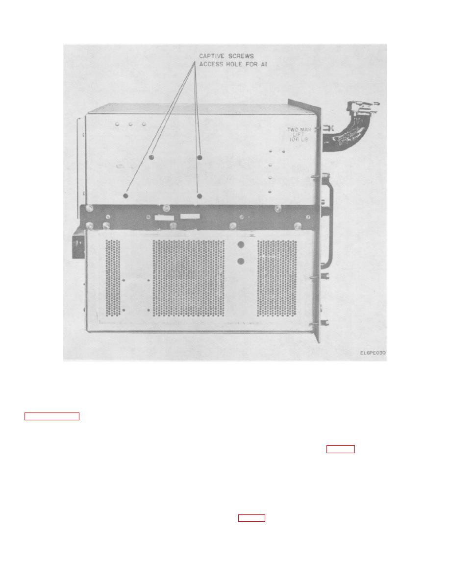
(8) Loosen the four captive screws which
waveguide flange to the shelter waveguide flange and
secure the module bracket. These captive screws are
free the mated flanges.
reached through access holes in the left side of the PA
(3) Remove the cables at the SHF IN and
SHF TEST OUT connectors.
5-18
