
TM11-5895-846-14
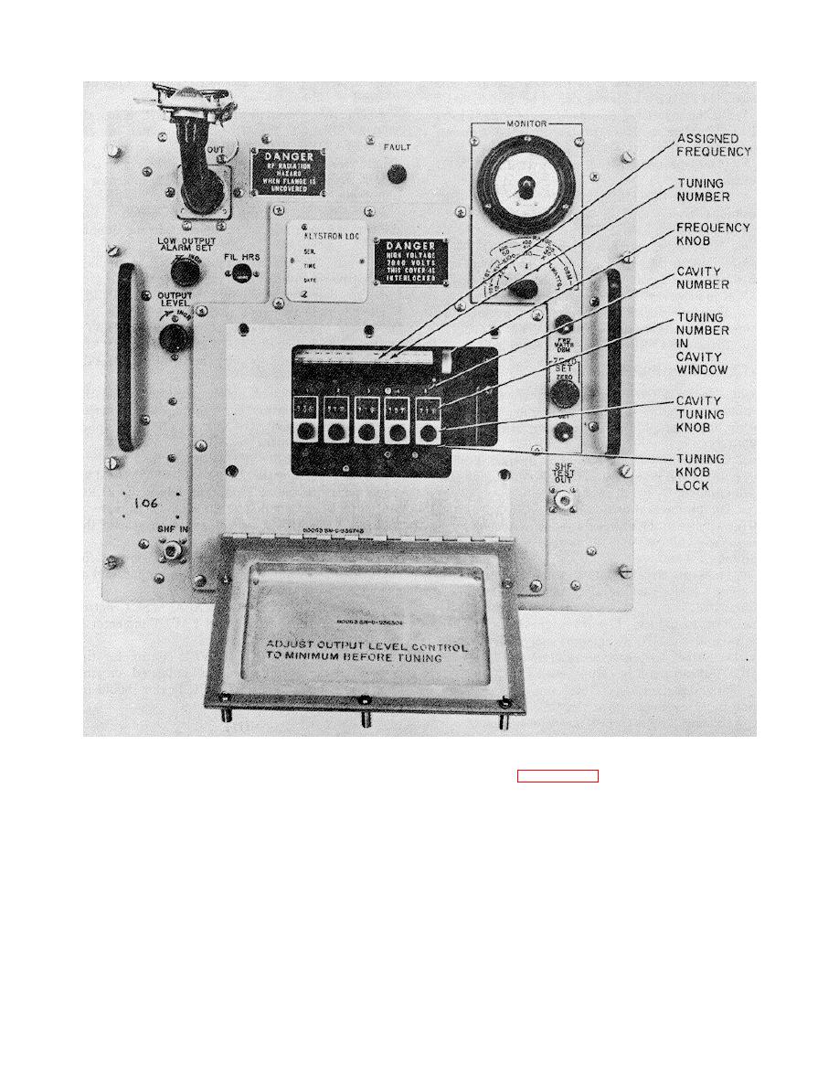
Figure 3-17. Klystron Frequency Chart and tuning Cavities.
e.
f.
Listed alongside each frequency entry
See figure 3-17. Unlock the tuning knob for
are five columns of 3-digit numbers which are related to
cavity 1 by pushing the tuning knob lock to the left.
the five cavity tuning knobs and windows below the chart.
Rotate the cavity tuning knob to the assigned tuning
The cavity tuning numbers (in this example) for 8225
number (715). Always approach this number from a
MHz are as follows:
clockwise direction and starting about 100 digits below it.
(each klystron has an applicable chart).
For example, rotate the cavity tuning knob to 615 (from
either direction) then rotate the knob clockwise up to
Cavity no.
715. Lock the tuning knob for cavity 1.
g.
Repeat step f above for cavities 2, 3, 4
(column)
3-digit tuning no.
1
715
and 5. The klystron is now tuned to the assigned
2
736
transmit frequency.
h.
3
755
Close and secure the KLYSTRON
4
736
TUNE cover.
5
766
i.
On the associated upconverter check
that the POWER circuit breaker is in the ON position.
3-31
